
5.1 Installation and placement of control units
Depending on the structural conditions, three different installation variants
are available. Neither the function nor the operating options are affected.
Decentralized device mounting
Decentralized device mounting is predominantly used in commercial and industrial buildings
and is particularly suitable for segment-oriented automation for flexible
use of space.
Some special features of this type of installation:
- SMI drives are connected in parallel
- Short cables to Drives
- Clear cable management
- Simple planning
- Easy retrofitting
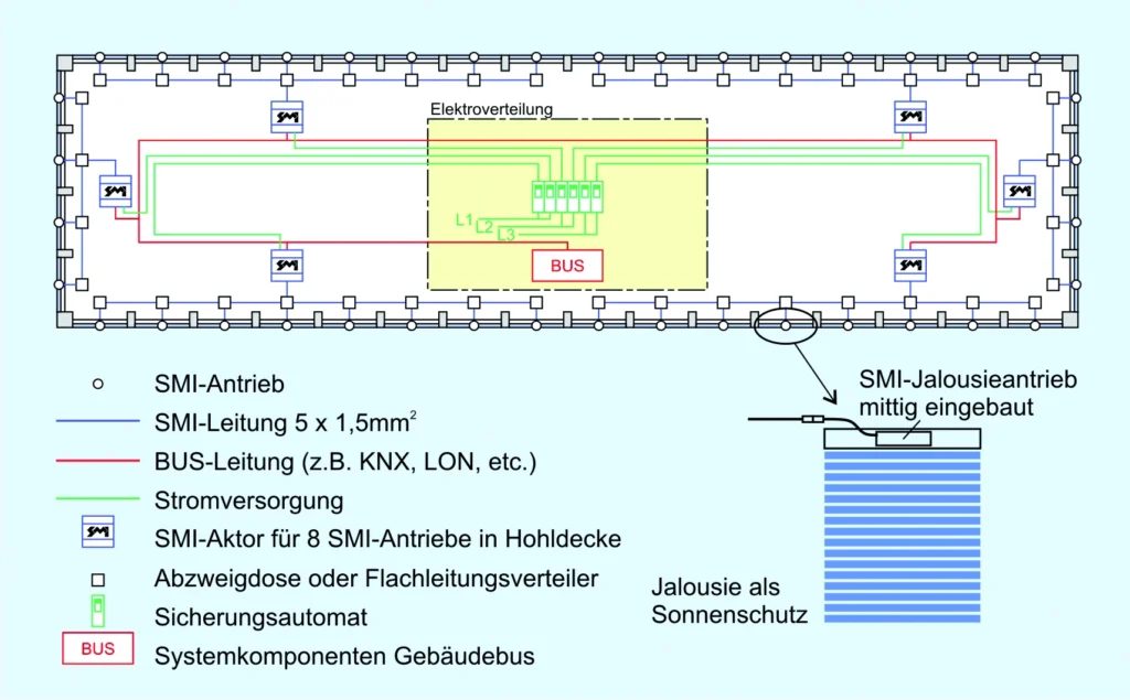
e.g. in the suspended ceiling.
Mounting in satellite station
Mounting in satellite stations (e.g. system distributors) is predominantly used in commercial and
industrial buildings, in production halls and in some cases in residential construction. The organization
of the satellites is usually based on a room, a group of rooms or a
façade section with a fixed number of axes.
Some special features of this type of installation:
- SMI drives are connected in parallel
- Short lengths of Drive cables
- Satellites are connected via bus system
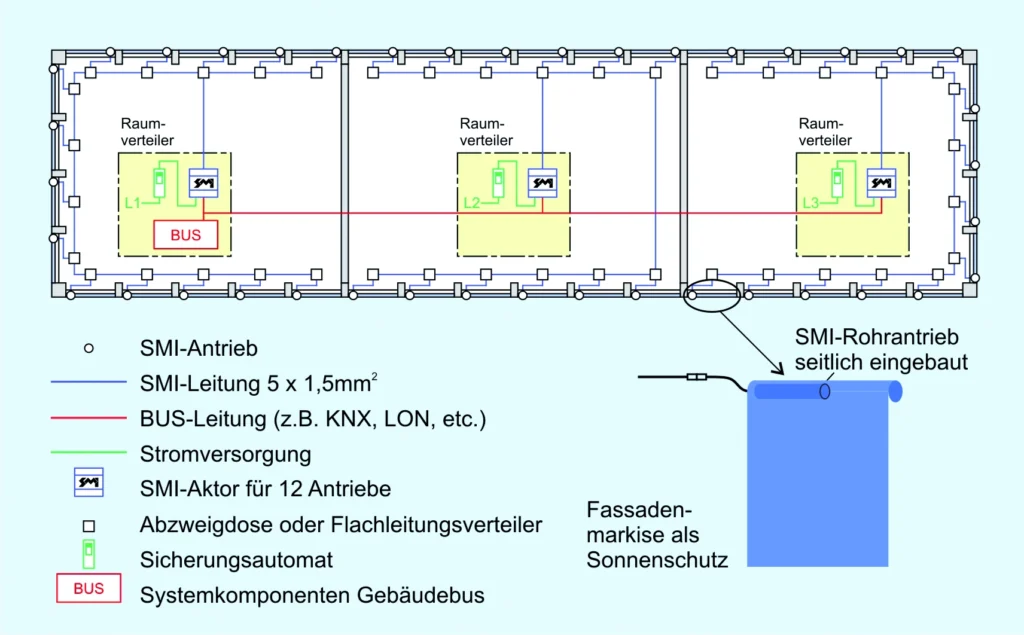
saves cabling.
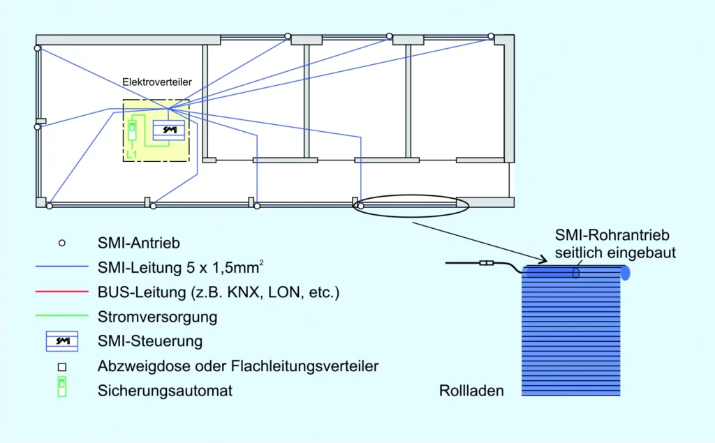
Centralized device mounting:
Centralized device mounting is predominantly used in residential and single-family homes.
Some special features of this type of installation:
- SMI drives are connected in parallel
- Short control cables in the electrical distribution board
- Service-friendly thanks to easy access to the control system. Centralized device mounting is often used in single-family homes.
5.2 Installation solutions for SMI drives
5.2.1 Flat cable for indoor use
For installing SMI drives indoors in buildings,
flat cable systems are ideally suited to achieve decisive installation advantages. The
“flexible” busbar combines the advantages of a busbar with the flexible routing
of a cable. With freely positionable adapter outlets, the SMI drives can be connected quickly and
easily to the flat cable. Contacting is carried out using
insulation-piercing screws. The flat cable is not interrupted,
eliminating the laborious cutting, stripping and connecting of the cables.
With this type of installation, sources of error can be virtually eliminated,
and installation times and costs can be significantly reduced.
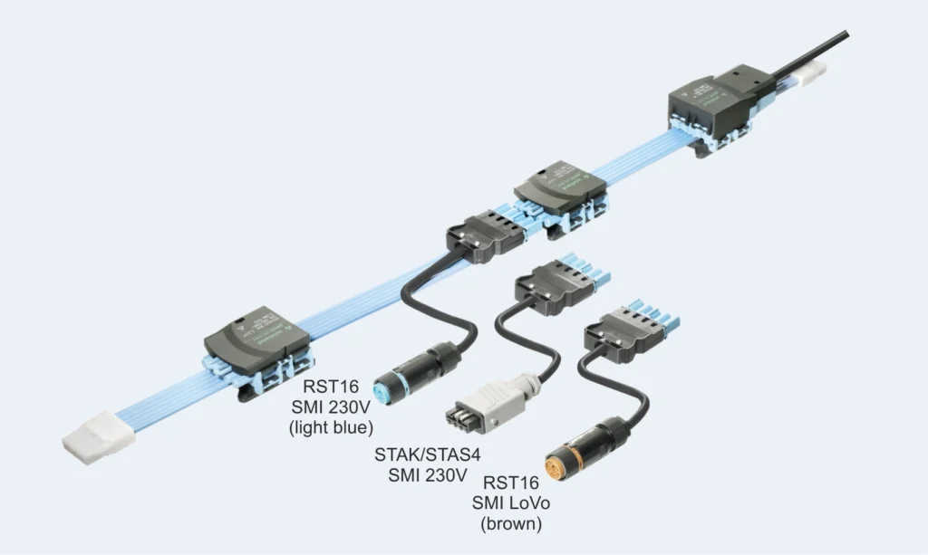
To clearly distinguish the SMI mains/bus cable from other circuits,
the cable, taps and plug connections are color-coded and mechanically keyed; incorrect
connections and misplugging are therefore excluded. For the SMI application, the
assignment of the 5-core flat cable is I+, I-, N, L, PE.
Indoor application:
With flat cable installation, the cable is routed along the SMI drives indoors in the building
and terminated at both ends with a flat cable end piece.
The flat cable is fed at any point via a feed-in module, from
which a round cable leads to the central sub-distribution board or to a decentrally mounted
field distributor.
A tap to the SMI drive can now be made at any point on the flat cable. This is
implemented with a 5-core outlet adapter in the color-coded SMI keying. The adapters also serve
to fix the flat cable in place. Using pre-assembled connection cables,
the SMI drives are connected via “plug&play”. The installation is therefore completed in the shortest possible time.
As the installation is indoors, it is implemented with protection class IP40
.
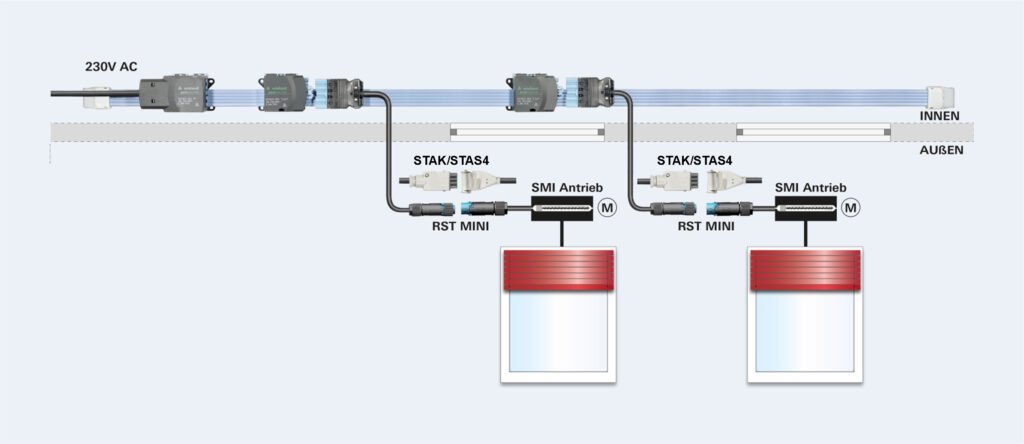
5.2.2 Pluggable installation for façade / outdoor area
For facade/outdoor use, the modular, pluggable solution is recommended. To protect
against environmental influences, a system with a high protection rating IP66/IP68/IP69 is used.
Distributors are pre-assembled at the factory on the façade elements or on the
sun-shading element; the connection on site is made with
pre-assembled cables in the corresponding segment length. For maintenance work,
the drives can be unplugged individually or simply replaced.
The function of the remaining drives in the line remains ensured. The supply to the
SMI drives only needs to be “interrupted” once for the 16 drives of a line. The
installation is therefore carried out completely outside the building envelope. The modularity of the installation
simplifies subsequent changes and extensions. The resulting
time savings increase the cost-effectiveness of the installation.
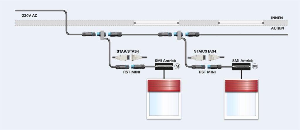
Image: Wieland Electric
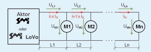
5.3 Cable sizing
To date, the sizing of cable cross-sections has assumed a 1:1 connection from
one control unit channel to one drive. Due to the possibility with SMI to connect up
to 16 drives in parallel, 1:n connections are now possible, i.e. from one channel
of a control unit, a number n of drives can be controlled. This means that
the currents flowing through the cable also increase by a factor of n.
Cable sizing must therefore be given appropriate attention.
From the control unit to the first drive, the sum of all rated Drive currents flows: n x IN;
between the first and second drive, a current reduced by one rated Drive current flows:
(n-1) x IN; up to the last drive, in which only the rated Drive current IN flows.
Due to the currents, different voltages (UL1, UL2, …
ULn) drop across the individual cable sections depending on the
length (L1, L2, … Ln) and cable cross-section, reducing the respective voltage at the drive (UM1, UM2, … UMn).
For mains-voltage drives, the rated voltage is 230V and the minimum supply voltage is
207V. The cables must be designed so that a voltage of
207 V is not undershot at the last drive.
Example calculation:
Mains-voltage drives 230 V | Rated Drive current: IN = 0.6A | Number of drives: n = 16
Total cable length: 200 m (even distribution across the individual cable sections)
Different boundary conditions may lead to different results and must be
taken into account on a project-specific basis.
| Drive | Cable cross-section | |||
|---|---|---|---|---|
| 0.75mm² | 1.0mm² | 1.5mm² | 2.5mm² | |
| M1 | 224 V | 226 V | 227 V | 228 V |
| M2 | 221 V | 224 V | 226 V | 227 V |
| M3 | 219 V | 221 V | 224 V | 227 V |
| M4 | 216 V | 219 V | 223 V | 226 V |
| M5 | 213 V | 217 V | 221 V | 225 V |
| M6 | 210 V | 215 V | 220 V | 224 V |
| M7 | 207 V | 213 V | 219 V | 223 V |
| M8 | 204 V | 211 V | 217 V | 222 V |
| M9 | 201 V | 209 V | 216 V | 221 V |
| M10 | 199 V | 206 V | 214 V | 221 V |
| M11 | 195 V | 204 V | 213 V | 220 V |
| M12 | 193 V | 202 V | 211 V | 219 V |
| M13 | 190 V | 200 V | 210 V | 218 V |
| M14 | 187 V | 198 V | 209 V | 217 V |
| M15 | 184 V | 196 V | 207 V | 216 V |
| M16 | 181 V | 194 V | 206 V | 215 V |
A calculation program is available at https://standard-motor-interface.com/technik-des-smi/